

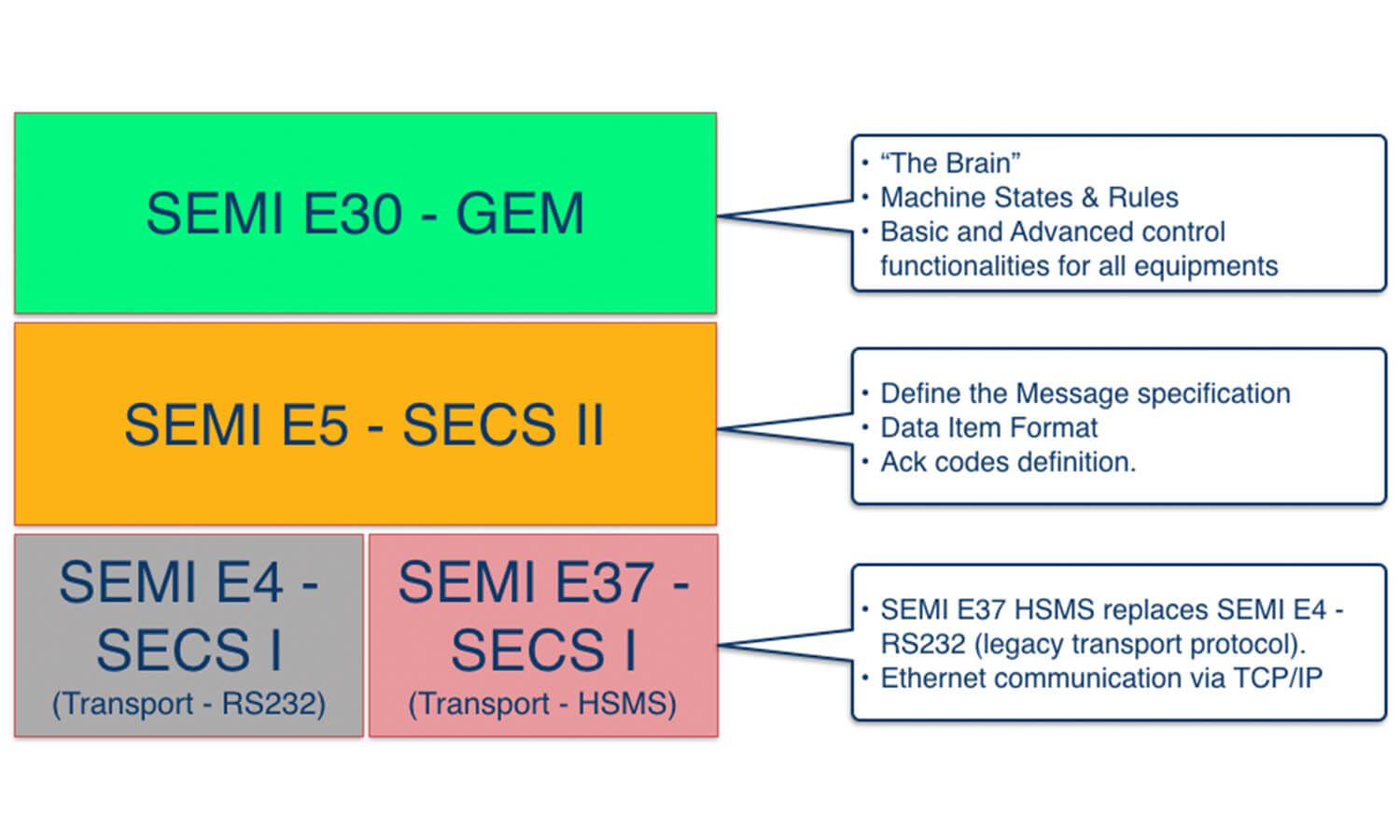
This guide provides a beginner-friendly introduction to SECS/GEM, the standard communication protocol used in semiconductor factory automation. You’ll learn what SECS/GEM stands for, how the three core standards (SEMI E30 GEM, SEMI E5 SECS-II, and SEMI E37 HSMS) work together, and how equipment communicates with factory host systems.
For semiconductor OEMs and fabs, SECS/GEM has moved from a nice-to-have to a baseline expectation. Leading customers now require GEM or GEM300 compliance before they accept a new tool, and factories running mixed equipment fleets depend on standardized communication to keep MES data flowing. If you are evaluating how to bring SECS/GEM to your equipment, explore SECS/GEM solutions for your fab to see how a proven SDK can shorten the path.
For the complete official standards, refer to SEMI.org. To implement SECS/GEM on your equipment without building a driver from scratch, see our NxSphere® GEM SDK.
Understanding SECS/GEM: Definition & Core Concepts
1.
SECS (SEMI Equipment Communication Standards) and GEM (Generic Model For Communications and Control Of Manufacturing Equipment) are standards published and maintained by SEMI.org, an international organization of semiconductor manufacturers that governs the standards for semiconductor manufacturing.
2.
SECS/GEM is the main communication protocol used in automation for the semiconductor and electronics industries, and today it has been widely adopted in photovoltaic and SMT industries as well.
3.
SECS/GEM provides a communication interface between equipment and host systems.
4.
Unlike other communication protocols such as PLC, SECS/GEM enables equipment from a variety of vendors to communicate with different types of host systems using a standard, consistent protocol.
Why SECS/GEM Integration Is Critical for Semiconductor Manufacturing
Without SECS/GEM, factory data lives in silos. Operators key readings into spreadsheets, alarms go unnoticed, and every new tool needs a bespoke integration, adding up to costly downtime and blind spots that erode yield. SECS/GEM changes the economics of automation.
Standardized communication enables real-time monitoring, faster tool onboarding, and cleaner analytics, which industry deployments link to significant integration cost reduction and measurable yield gains.
For OEMs, GEM compliance is often a precondition of the sale. For fabs, SECS/GEM solutions are the shortest route from equipment on the floor to actionable data, and SECS/GEM gateway solutions handle the legacy and PLC-driven tools that would otherwise stay stranded.
SECS/GEM Standards
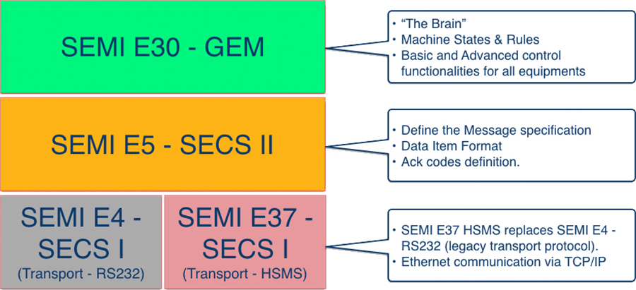
Three SEMI standards work together to make SECS/GEM communication possible: SEMI E30 GEM defines what the equipment does, SEMI E5 SECS-II defines how messages are structured, and SEMI E37 HSMS defines how those messages travel over the network. Understanding how the three fit together clarifies both the protocol and the products built on it.
The SEMI E30 GEM Standard Explained
The GEM standard defines a common set of equipment behavior and communications capabilities that provide the functionality and flexibility to support the manufacturing automation programs of semiconductor device manufacturers. Equipment suppliers may provide additional SECS-II functionality not included in GEM, as long as the additional functionality does not conflict with any of the behavior or capabilities defined in GEM. Such additions may include SECS-II messages, collection events, alarms, remote command codes, processing states, variable data items (data values, status values or equipment constants), or other functionality that is unique to a class (etchers, steppers, etc.) or specific instance of equipment.
Communication
The COMMUNICATION state model defines the behavior of the equipment in relation to the existence or absence of a communication link with the host. It also defines how communication is established or re-established with S1F13/S1F14 when communication is broken.
What this means in practice: The communication state model gives you a predictable way to detect and recover from connection loss between host and tool. For fabs, that means fewer silent failures and cleaner uptime. For OEMs, it means customers can trust the equipment will reconnect and resume reporting without operator intervention.
Control
OFFLINE (Lowest Level): Operation of the equipment is performed manually by the operator at the operator console. Equipment will respond with an SxF0 to any primary message from the host other than S1F13 or S1F17.
ONLINE/LOCAL (Middle Level): In this state, the host is only allowed to perform "read-only" operations like data collection. The host shall be prohibited from modifying any equipment constants that affect processes, or issuing remote commands that cause physical movement or initiate processing.
ONLINE/REMOTE (Highest Level): In this state, the host may operate the equipment to the full extent available through the communications interface ("read-write" operations).
Processing
Remote Command
Variables
The GEM standard defines three types of variable which are accessible by the host:
Status Variable: A "read-only" global variable defined in the equipment. Whenever processing occurs, the equipment updates the respective status variable to reflect the latest data, e.g. increments of a counter, current or previous state, etc.
Equipment Constant: A "read-write" global variable defined in the equipment. The host can set or modify the equipment constant, which may affect settings that in turn change the way the equipment behaves.
Discrete Variable: A "local" variable which only exists in a collection event.
Data Collection
SECS/GEM provides several avenues for the host to collect data or information from the equipment:
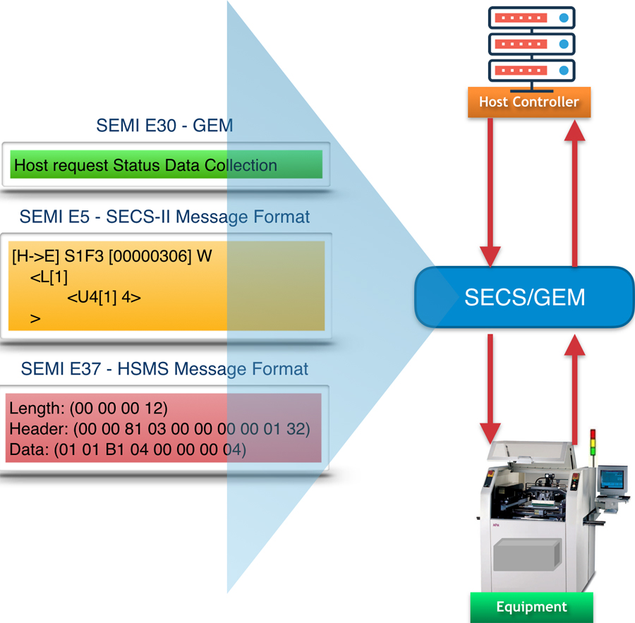
A set of status variable values can be requested at any time using the S1F3 command.
A set of equipment constant values can be requested at any time using S2F13.
The host can define a report containing status variables, equipment constants, and data variables, then attach it to a collection event. When the equipment raises the event (using the S6F11 command), the report containing those variable values will be sent together.
The host can define traces which sample status variable data periodically.
Another way is to leverage alarm notification to collect more data with a collection event. By standard, whenever an alarm occurs or clears, a collection event must be sent to the host.
Alarm Notification
This feature allows the equipment to notify the host of every occurrence or clearance of an alarm or error on the equipment. Alarm refers to occurrences that are abnormal, undesirable, or that endanger people, equipment, or physical material being processed.
Below are some characteristics of Alarm Management defined by GEM:
Each alarm has two associated states: ALARM SET (occurrence) and ALARM CLEAR (clearance).
Each AlarmSet and AlarmClear has an associated collection event. This addresses the host's potential need for more extensive and flexible data reporting.
The host can request which alarms to be enabled or disabled, and the equipment will only notify the host for the enabled alarms.
Documentation
And Many More...
Please refer to the complete standard for other features such as Spooling, Process Program, Terminal Services, and Limit Monitoring.
SEMI E5 SECS-II Message Structure
As described in the introduction, this standard provides the APIs for interfacing between host and equipment. In this standard, each message is represented as a Function and grouped in a Stream (category).
Like a web service, each SECS-II message consists of a Header (which typically contains the method or function name and transaction type: request or reply) and a Body (which specifies the parameter’s name and type). In some functions, the Body may be empty.
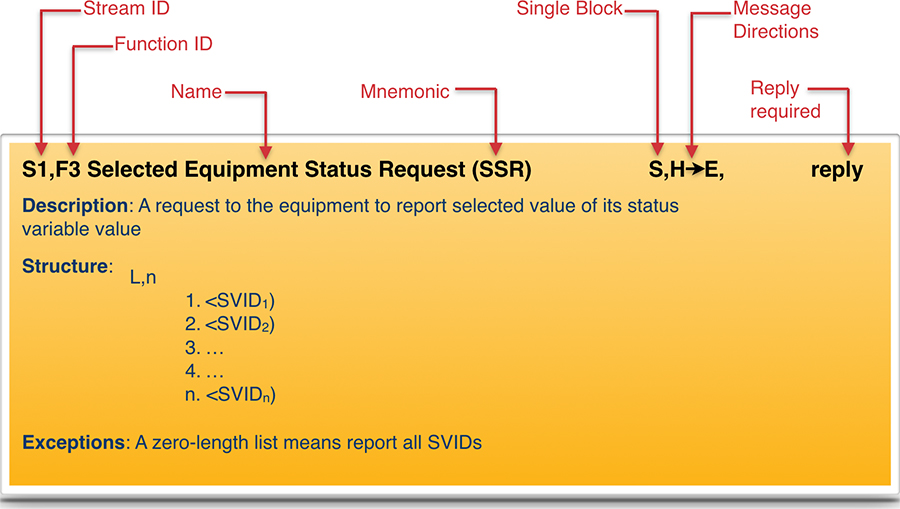
Below describes the convention of the SECS-II Message Structure.
Message Header
Where:
Stream ID = Message stream or category
Function ID = Function identifier of the message. Each stream has multiple functions. An odd Function ID denotes a Primary message (request) while an even Function ID (SnFm+1) denotes the Secondary or Reply message.
Mnemonic = Short form of the message
S, M = S=Single, M=Multi-block
H, E = H=Host, E=Equipment
Message Directions = Denotes the valid message direction. Some messages are valid for a single direction only (e.g. H->E or H<-E), however certain messages can be bi-directional (HE). E.g. S1F13 Establish Communication (HE).
Reply = Denotes whether or not the message requires a reply.
Description
Structure
The function’s message body. Detailed structure showing lists and defined items. Lists are denoted by a capital L followed by the length separated by a comma. The individual elements in the list are numbered on separate lines.
Nested lists are indented to emphasize the structure. The detailed form of the items is given in the define section at the beginning of the transaction. The symbols “<” and “>” are used to mark item headers. A detailed description of each data item, as well as a list of the allowable data formats, can be found in the Data Item Dictionary.
Exception
SEMI E37 HSMS: High-Speed SECS Message Services
HSMS is the transport layer built on top of the TCP/IP protocol. HSMS is intended as an alternative to SEMI E4 (SECS-I) for applications where higher-speed communication is needed or where a simple point-to-point topology is insufficient.
TCP/IP Settings
As HSMS is derived from TCP/IP, the following settings are required for both host (client) and equipment (server):
ConnectionMode: ACTIVE or PASSIVE mode. ACTIVE Mode is normally on the host side while PASSIVE Mode (Listening) is on the equipment side. However there is no restriction against using it the other way.
Local IP Address and Port Number: Required for any entity operating in PASSIVE mode. Determines the address on which the local entity will listen for incoming connection requests. Equipment typically operates in this mode.
Remote IP Address and Port Number: Required for any entity operating in ACTIVE mode. Determines the address of the remote entity to which the local entity will attempt to connect. The host typically operates in this mode.
HSMS Timeout Settings
Implementations of HSMS must provide installation-time settings for the following parameters:
T3 Reply Timeout: Specifies the maximum amount of time an entity expecting a reply message will wait for that reply.
T5 Connection Separation Timeout: Specifies the amount of time which must elapse between successive attempts to connect to a given remote entity.
T6 Control Transaction Timeout: Specifies the time which a control transaction may remain open before it is considered a communications failure.
T7 Not Selected Timeout: Specifies the time a TCP/IP connection can remain in NOT SELECTED state (i.e., no HSMS activity) before it is considered a communications failure.
T8 Network Inter-character Timeout: Maximum time between successive bytes of a single HSMS message.
Frequently Asked Questions About SECS/GEM
What is the difference between SECS/GEM and older communication protocols?
SECS/GEM is the semiconductor industry standard adopted by more than 100 OEMs worldwide. Older protocols such as proprietary APIs, manual data entry, and RS-232 serial lack real-time capabilities, do not scale, and create vendor lock-in. SECS/GEM is standardized, real-time, and equipment-agnostic, making SECS/GEM the foundation of modern fab automation.
Can legacy semiconductor equipment use SECS/GEM?
Yes. Legacy equipment 10 to 20+ years old typically lacks native SECS/GEM support, but can be retrofitted through gateway middleware or SDK-based drivers. NxSphere® GEMBridge and NxSphere® GEM are designed specifically for legacy device integration, allowing existing tools to communicate with modern fab automation systems without replacement.
How long does SECS/GEM integration typically take?
SECS/GEM integration timelines vary by equipment complexity and gateway type. Simple gateway deployments take 2 to 4 weeks; SDK-based integrations across multiple tools typically take 6 to 12 weeks. Insphere prioritizes high-impact equipment first, so ROI arrives incrementally.
Ready to Implement SECS/GEM?
Whether you are shipping a new tool that must be GEM-compliant on day one or bringing an existing fleet online for MES connectivity, the right SDK and gateway can turn a months-long project into a weeks-long one. Insphere.s SECS/GEM solutions are built on 15+ years of production deployments across leading fabs and OEMs.